Home / News / Industry news / Sandwich Panel Production Line: Equipment, Layouts and Selection Guide
Sandwich Panel Production Line: Equipment, Layouts and Selection Guide
Industry news-
Picture a cold-store panel plant quoting a 9 m freezer panel order on a line that was bought for garage doors: two mould stations, a low-pressure foaming unit and a manual lid. Fill time drifts, core density creeps up at the injection end, and the panel bows slightly after demoulding. Nothing is broken. The line was simply never designed for that panel.
The conclusion comes first: on a sandwich panel production line, the layout decides which orders you can accept, and the metering unit decides how repeatably you can hold them. Thickness range, core chemistry and blowing agent are refinements on top of that sequence, not substitutes for it.
What follows covers the four decisions that carry the most weight: continuous versus discontinuous layout, panel build-up and core chemistry, the specification of the foaming machine, and the blowing-agent route. Where a figure appears, it is either a published industry value or a calculation you can repeat in a spreadsheet.
Continuous or Discontinuous: The Layout Decision Comes First
Both line types make the same product. The difference is how the foam is introduced and how long it is restrained. A continuous double-belt line meters foam onto the running bottom facing, lays the top facing over it, and holds the rising foam to thickness under belt pressure until it cures. A discontinuous multi-station line fills a closed mould with a metered shot and keeps it under a press for the cure.
That one difference cascades into throughput, product mix, scrap rate and capital. The table below is the version worth pasting into a supplier meeting.
Indicative comparison of continuous and discontinuous panel lines; confirm speeds, panel lengths and changeover times against each supplier's own specification.
Decision point
Continuous double-belt line
Discontinuous multi-station line
Foam introduction
Poured onto the moving bottom facing; top facing applied before the belt
Metered shot injected into a closed mould
Output
Set by belt speed, typically 3 to 15 m/min
Set by mould count and cure time
Panel length
Cut to length, commonly up to 13.5 m
Limited by mould length
Thickness change
Slow, and changeover generates scrap
Spacers or mould change, quick
Product mix
Long runs of one or two panel types
Mixed orders, doors, cold rooms, short runs
Capital and floor space
Highest
Moderate to lower
Best fit
Volume wall and roof panels
Custom and mixed production
Read the last row first. When one or two panel types in one thickness dominate the order book, a continuous line earns its capital. When facing, core or thickness changes several times a month, a discontinuous line usually wins on total cost even though it looks slower on paper.
From Coil to Stacker: The Stages That Decide Panel Quality
Strip the line down and there are six stages. Panel complaints almost always trace back to one of them, and rarely to the one the operator blames first.
Facing feed and pre-heat. Steel facings of 0.4 to 0.6 mm are decoiled, levelled and warmed, commonly to about 35 to 45 C, so the foam skins against a warm surface instead of a cold one.
Edge sealing and side dams. Edges are closed before the foam arrives. End voids are usually a sealing fault, not a chemistry fault.
Metering and injection. Components are dosed, temperature-conditioned, mixed at high pressure in the mixing head and injected. Shot size, ratio and pour pattern decide whether the cavity fills evenly.
Rise and cure under restraint. The belt, or the press lid, holds the expanding foam at the target thickness until it can carry load.
Cut-off and trimming. A flying saw cuts to length on continuous lines; both line types then trim to final width.
Cooling and stacking. Panels are stacked flat for post-cure. Stacking too early is a common cause of dimensional drift.
How the panel is built up
Two facings, one core, and an edge profile that has to survive handling and site assembly. The exploded view below shows the layers a foaming station actually has to fill.
Figure 1: Exploded isometric view of a metal-faced sandwich panel. Facings are typically 0.4 to 0.6 mm steel or aluminium.
Core Chemistry and Thickness: Where the Thermal Numbers Come From
Rigid PIR foam is commonly declared at around 0.021 to 0.023 W/mK and PUR at 0.022 to 0.026 W/mK, both well below XPS at 0.029 to 0.035, EPS at 0.031 to 0.038 and mineral wool at 0.035 to 0.045. The spread inside a family matters as much as the gap between families: the same PUR formulation can move by roughly 10% depending on blowing agent, cell structure and density.
Thermal conductivity of common panel cores (W/mK, typical declared values)
Figure 2: Lower bars mean better insulation per millimetre. Values are typical published declarations; each supplier's Declaration of Performance is the binding figure.
Thickness then does the rest of the work, but not linearly in a finished building. The chart below uses pure conduction at lambda = 0.024 W/mK.
U-value against panel thickness (lambda = 0.024 W/mK, conduction only)
Figure 3: Going from 40 mm to 100 mm cuts calculated heat loss by about 60%; going from 100 mm to 200 mm cuts it by a further 50%. Real panels perform worse than this because EN 14509 declared values include ageing and thermal bridge corrections, and joints and fixings add losses on site.
The Metering Unit: Shot Accuracy Beats Nominal Output
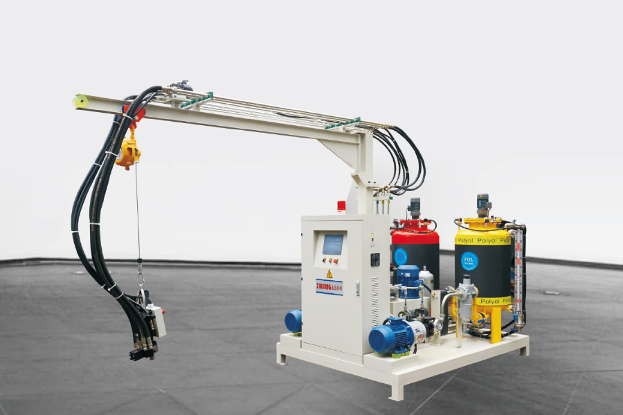
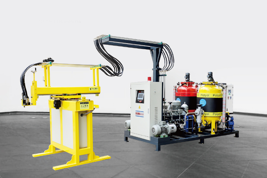
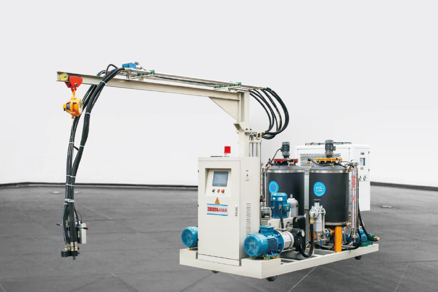
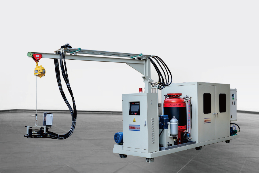
High-pressure heads mix by impingement, with injection pressures typically quoted between 100 and 200 bar, against roughly 5 to 30 bar for low-pressure stirring. The practical difference on a panel line is cell structure and shot repeatability: a high-pressure head fills a long, thin cavity with less density variation from end to end.
Suppliers commonly quote ratio accuracy of about 1% and shot repeatability in the region of 1 to 1.5%. Ask for the coefficient of variation over 20 consecutive shots on your own formulation, not the headline figure on the datasheet. Component temperature control matters just as much, with most panel formulations running best when both components are held at roughly 20 to 25 C within about 2 C.
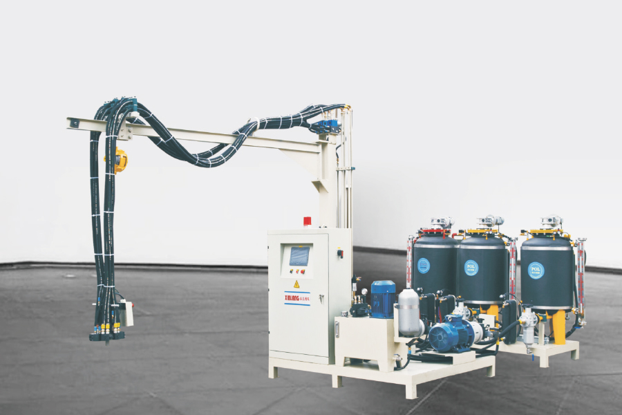
Overpacking is the quiet cost on this kind of line. Filling 5 to 10% above the theoretical minimum density is common on an untuned machine, and it is the fastest cost to attack because it shows up in every panel. Three-component machines add a third stream for additives such as flame retardants, pigments or nucleating agents without pre-blending them into the polyol, which is worth considering if your PIR formulations change often.
Shot weight range matched to the largest panel cavity, with a stated repeatability figure.
Ratio range wide enough for your formulations; most panel work sits between 1:1 and about 1:1.6 polyol to isocyanate.
Throughput in kg/min that matches the fastest belt speed or the shortest cycle you intend to run.
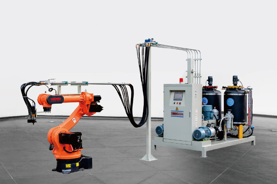
Mixing head count and traverse arrangement, so one head does not become the bottleneck.
Recipe storage in the PLC, so a thickness change is a stored setting rather than a manual reset.
Line Layouts for Panel Moulds: Annular, H-Type and Turntable
Cycle math first: throughput equals the number of mould stations divided by the cycle time. Adding stations is almost always cheaper, safer and faster than shortening cure time through chemistry.
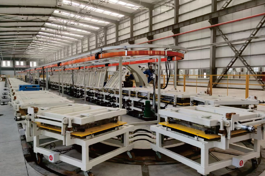
Annular (ring) line. Moulds travel a closed loop, with foaming stations inside the ring and operators outside. Floor space per station is efficient and long runs of one panel type flow well.
H-type line. Two mould rows share a central aisle and a travelling injection head. Tool changes and short runs are easier to schedule than on a closed ring.
Turntable line. Radial stations on a rotating table. Compact and quick to commission, and a good match for shorter panels, doors and smaller batches.
Whichever layout you choose, the mould is part of the quality system. Mould temperature uniformity across a 9 m cavity, lid stiffness and release-agent discipline affect bowing and surface finish more than most buyers expect at the quotation stage.
Blowing Agents, Pentane Safety and Fire Performance
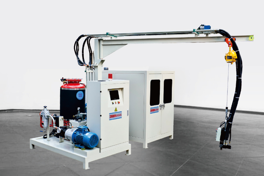
Cyclopentane has an ozone depletion potential of zero and a global warming potential far below the HFCs it replaces. Published 100-year figures put HFC-141b at roughly 700 and HFC-245fa at about 1,000, while hydrocarbons sit in the low tens. Under the EU's revised F-gas Regulation (EU) 2024/573 the HFC route is being squeezed further, which is why hydrocarbon systems keep gaining share in panel foam.
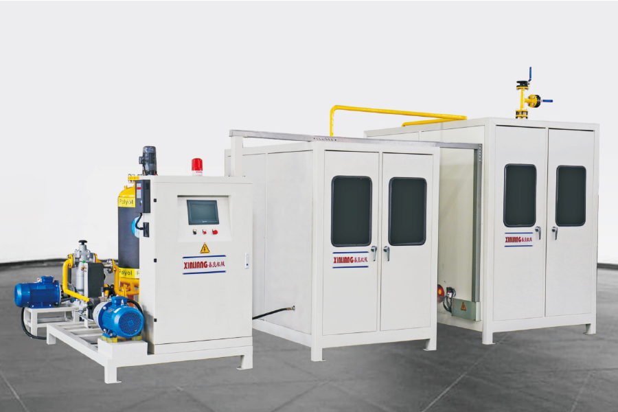
Pentane is flammable, and that changes the plant, not just the machine. Expect explosion-proof electricals in the foaming zone, mechanical ventilation, gas detection, grounding and bonding, and no ignition sources anywhere near the mixing head. A pre-mix system keeps pentane concentration and temperature stable before dosing, which is what makes the shot repeatable from the first panel of a shift to the last.
Fire performance is a separate conversation from thermal performance. Panels are classified to EN 13501-1; many PIR systems are tested to B-s1,d0, PUR systems commonly land at B-s2,d0 or B-s3,d0, and mineral wool cores reach A2-s1,d0. Classification is system-specific and thickness-specific, so always read the Declaration of Performance for the exact build-up you are selling, and never assume a core chemistry alone guarantees a class.
Defects to Watch and What to Inspect Before Sign-Off
Six defects account for most panel complaints, and each one has a short list of first checks.
End voids and unfilled corners. Check edge sealing and pour pattern before touching the formulation.
Density gradient along the panel. Usually shot size, injection position or mould temperature.
Delamination and bowing. Facing temperature, release agent, demould too early, or overpacking.
Shrinkage lines and sink marks. Gel time mismatch between the two components.
Thickness variation. Belt or spacer control, and lid stiffness on discontinuous lines.
Surface read-through. Almost always overpacking on a thin facing.
For a factory acceptance test, ask for the following in writing:
Shot weight coefficient of variation over 20 consecutive shots on your formulation.
Core density measured at three positions across a full-length panel, not at the injection point only.
Length, width and thickness tolerances checked against the EN 14509 tolerance table.
Peel adhesion between foam and facing on a cut sample from both ends of the panel.
Repeatability of a thickness change, including how many panels are scrapped during the changeover.
Frequently Asked Questions About Sandwich Panel Production Lines
Q1. What is a sandwich panel production line?
It is the equipment set that turns two metal facings and a foam core into an insulated panel: facing feed, edge sealing, a foaming or injection machine, a curing section such as a double belt or a press, then cut-off, trimming and stacking.
Q2. How many panels can a line produce per shift?
On discontinuous lines, throughput equals mould stations divided by cycle time, so a 20-station line with a 10-minute cycle produces roughly 120 panels an hour at its theoretical rate. Real output is lower after changeovers and scrap; always calculate from your own panel size.
Q3. PUR or PIR core for a sandwich panel?
PUR is usually cheaper and meets standard cold-room and wall requirements. PIR is chosen when fire performance or higher service temperature matters, and it is commonly tested to a better EN 13501-1 class than PUR, but at a higher formulation cost.
Q4. Can a sandwich panel line run cyclopentane instead of HFC?
Yes, and many new lines do. It requires an explosion-proof foaming area, ventilation, gas detection and a pre-mix or dosing system, so retrofit cost is real. The payoff is regulatory stability and a GWP far below HFC-141b or HFC-245fa.
Q5. What foam density should a sandwich panel core have?
Most metal-faced PUR and PIR panel cores are specified in the region of 38 to 45 kg/m3. Below that, mechanical properties and dimensional stability fall away; well above it, you are paying for material that adds little insulation value.
Q6. Continuous double-belt or discontinuous line for cold storage panels?
Cold rooms suit discontinuous lines well because required lengths and thicknesses vary widely and order volumes are moderate. Continuous double-belt lines make sense when one or two panel types dominate the order book and volumes justify the capital.
Before you sign anything, ask for two documents: a shot-weight repeatability record from a machine that is already running, and a factory acceptance test on your own formulation at your intended thickness. Those two records tell you more about a sandwich panel production line than any brochure.
If you are still mapping the process sequence, our buyer guide to PU foam production equipment walks through the equipment order and the questions to ask at each stage. Ningbo Xinliang Machinery supplies the metering unit, the line layout and the blowing-agent system as one package, sized to your panel range and output target.


 English
 русский
 عربى
عربى