Home / News / Industry news / Polyurethane Foam Manufacture: Process, Equipment, and Line Selection Guide
Polyurethane Foam Manufacture: Process, Equipment, and Line Selection Guide
Industry news-
A refrigerator plant that decides to bring cabinet foaming in-house usually starts with the same question: what does polyurethane foam manufacture actually demand if the target is stable density, no voids and a demold time under five minutes? The answer is rarely printed on a machine datasheet. It lives in the mix ratio, the temperature of the two components and the way the shot is laid into the cavity.
The short version: polyurethane foam manufacture is a precision metering process attached to a chemical reaction. Control the ratio, the mixing energy and the injection pattern, and the foam behaves predictably. Lose control of any one of them, and no amount of mold pressure will rescue the part.
The sections below follow the process from raw material tanks to the demold station, explain where high-pressure and low-pressure systems diverge, and set out which equipment configuration suits which production scale.
Two liquid streams meet at the mixing head. The A-side is a polyol blend: polyol, catalyst, surfactant, blowing agent and, in many rigid formulations, water. The B-side is an isocyanate, most often polymeric MDI for rigid foam or an MDI/TDI blend for flexible grades. Everything downstream of the mixing head exists to deliver those two streams at the correct ratio, temperature and pressure at the correct moment.
The ratio deserves more attention than it usually gets during a purchase. Rigid foam is commonly run at an index between about 100 and 110, where the index compares the actual isocyanate charge with the stoichiometric requirement. A drift of a few percentage points shifts cell structure, compression strength and demold behavior, and it is very hard to correct once the foam has risen.
The four stages every shot passes through
Cream time: the liquid clouds and begins to expand as the blowing agent vaporizes and the reaction starts.
Gel time: the polymer network builds enough strength to hold the gas bubbles in place.
Rise time: the foam expands to fill the cavity, driven by the blowing agent and by the carbon dioxide from the water-isocyanate reaction.
Cure and demold: the part gains enough green strength to be removed without distortion.
Those windows are set by the formulation, but they are only reproducible when the machine repeats the same shot weight, ratio and mixing quality on every cycle.
The Manufacturing Sequence, Step by Step
On a well-run line, polyurethane foam manufacture follows a fixed sequence whether the part is a refrigerator cabinet or a car seat pad.
Condition the raw materials. Polyol and isocyanate sit in jacketed tanks, usually held around 20 to 25 degrees Celsius, with dry nitrogen blanketing the isocyanate to keep moisture out.
Meter the two streams. High-pressure systems use axial piston or gear pumps, and each component is calibrated by weight before production starts.
Build pressure and recirculate. Both streams circulate back to the tanks at full working pressure so the head is ready for an instant shot.
Mix by impingement. In a high-pressure head the two streams collide at high velocity in a small chamber and mix within milliseconds.
Inject into the mold or cavity. Shot weight, pour pattern and injection time decide whether the cavity fills evenly or traps air.
Allow rise and gel. Mold temperature and venting determine whether foam reaches the corners without internal voids.
Demold, cure and inspect. Parts are trimmed, weighed and checked for density and surface quality.
The diagram below shows how those steps map onto a typical high-pressure foaming installation.
High-Pressure vs Low-Pressure Foaming: Where the Line Differs
The single biggest equipment decision is the mixing principle, because it shapes maintenance routines, solvent use and the minimum shot size the line can handle reliably.
Comparison based on the working principles described in polyurethane foaming equipment specifications.
The Core Machine: Choosing a Foaming Injection Unit
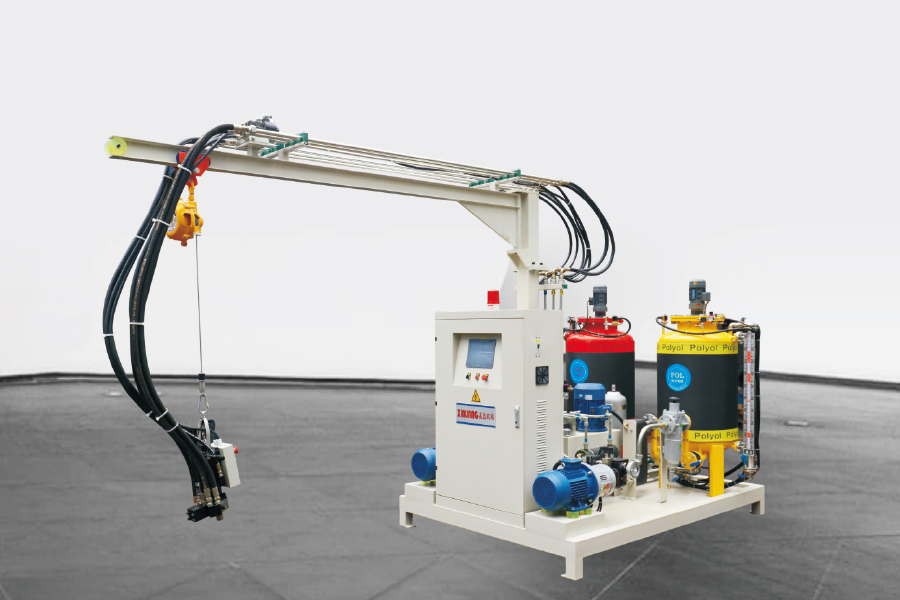
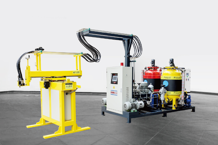
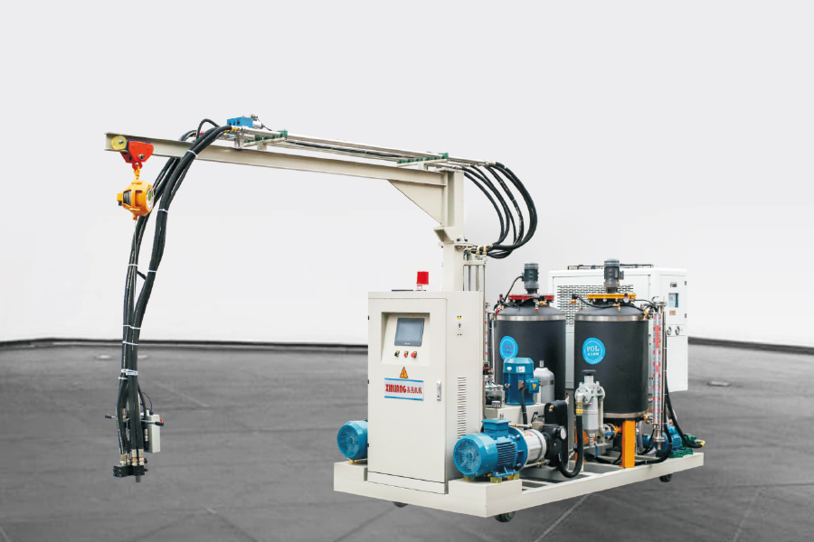
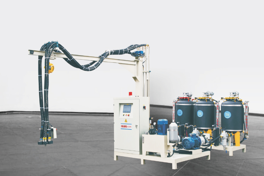
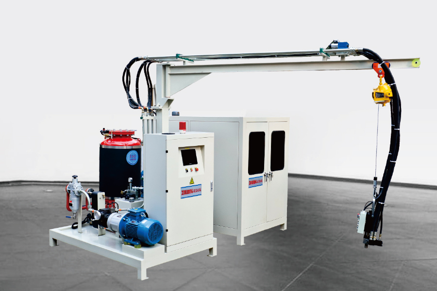
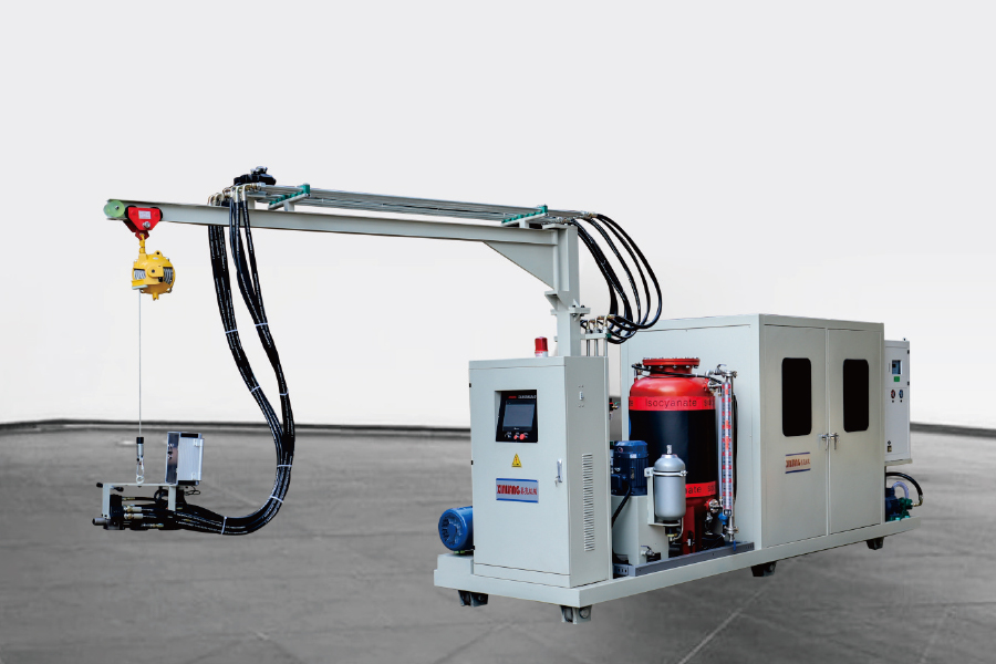
Most plants start with a single high-pressure injection machine and add automation later. The first decision is two-component or three-component: a two-component unit meters polyol and isocyanate, while a three-component unit adds a third stream, typically a blowing agent, pigment or additive that cannot be pre-blended into the polyol.
Fixed head: the lowest cost arrangement, suited to a single mold position or a stationary fixture.
Track-mounted head: the head travels along the mold line, so one machine can serve several stations in sequence.
XY-axis manipulator: a programmed pour path over a flat mold, useful for panels and shallow cavity shapes.
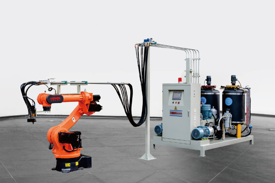
Six-axis robot: repeatable three-dimensional pour patterns, normally chosen where part geometry changes often.
Payback usually comes from repeatability rather than raw speed. A machine that holds shot weight inside a tight band reduces scrap and overpacking far more reliably than one that simply cycles faster.
Line Layout: When Output Volume Changes the Configuration
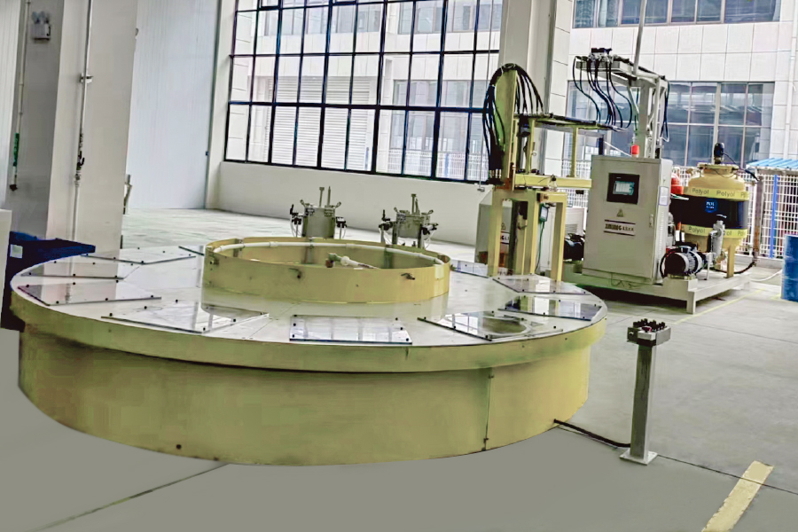
A single machine and a fixed mold work well up to a point. Once demold time is shorter than the time needed to load, close, foam, cure and unload one mold, that mold can no longer keep the machine busy. This is the gap that line layouts are designed to close, and it is the reason the polyurethane foaming equipment range splits into several architectures.
Turntable lines: molds index through load, foam, cure and unload positions, which suits a fixed takt time and a small number of identical parts.
H-type lines: mold carriers move along two parallel rails, giving a longer curing path and more stations without a large floor footprint.
Annular lines: a continuous loop for high-volume production where the same part runs for months at a time.
Choose on takt time and part mix. A plant running many different parts usually gains more from quick mold changeover than from a longer curing loop.
Cyclopentane and Blowing Agent Choices
Blowing agent selection drives both insulation performance and the safety equipment around the line. Cyclopentane has become the common choice for refrigerator cabinets and rigid insulation panels because of its low global warming potential, but it is flammable, which changes ventilation, electrical classification and material handling procedures on site.
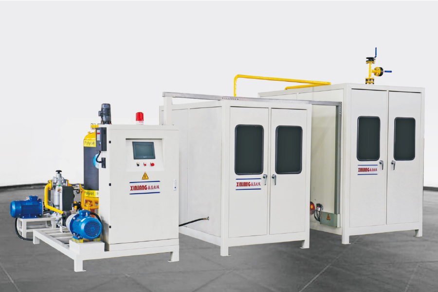
A cyclopentane premix system blends the blowing agent into the polyol under controlled temperature and pressure, so the mixed polyol reaches the injection machine already carrying the blowing agent. Compared with injecting liquid cyclopentane separately at the mixing head, premixing gives a more uniform cell structure and keeps the concentrated flammable liquid inside a closed loop.
For plants converting away from older fluorocarbon systems, the premix route is often the more manageable path, because the existing injection machine can frequently be retained with updated seals and revised control parameters.
Process Variables That Decide Foam Quality
Once the equipment is installed and calibrated, a handful of variables account for most quality problems:
Mix ratio drift caused by worn pump seals, viscosity changes or incorrect calibration.
Component temperature that falls outside the formulation window and shifts reactivity.
Injection pressure that is too low for full impingement mixing, producing streaks or coarse cells.
Pour pattern and shot weight that leave air pockets or overpack the cavity.
Mold temperature and venting that decide surface quality and cycle time.
Most defects, from voids and short shots to density variation and surface blisters, trace back to one of those five. Working through them in order is faster than adjusting parameters at random, and common PU foam defects and their fixes is a useful checklist when a fault first appears.
Frequently Asked Questions About Polyurethane Foam Manufacture
Q1. What is polyurethane foam manufacture?
It is the process of reacting a polyol blend with an isocyanate in the presence of a blowing agent, then shaping the expanding foam inside a mold or cavity. The reaction takes seconds, so ratio, temperature and mixing quality decide the final result.
Q2. What is the difference between high-pressure and low-pressure PU foaming machines?
High-pressure machines mix by impingement at roughly 100-200 bar and are usually self-cleaning between shots. Low-pressure machines stir the components mechanically at about 5-20 bar and generally need solvent flushing of the mixing chamber.
Q3. How do I choose between a single foaming machine and a production line?
Compare demold time with the time needed to load and unload one mold. If one mold cannot keep the machine occupied, a turntable, H-type or annular line is the usual answer; otherwise a single machine or a track-mounted unit is enough.
Q4. Which blowing agent is used for rigid PU foam insulation?
Cyclopentane is the mainstream choice for refrigerator cabinets and rigid panels because of its low global warming potential. HFO and HFC grades remain in use where a non-flammable system is required by the application.
Q5. Is a cyclopentane premix system necessary?
For most cyclopentane lines, yes. The premix system blends the blowing agent into the polyol under controlled conditions, which improves cell uniformity, reduces flash-off losses and keeps the flammable liquid inside a closed loop.
Q6. How can a manufacturer reduce material waste in PU foam production?
Calibrate both pumps by weight each shift, hold component temperatures steady, match the pour pattern to the cavity and avoid overfilling the mold. Most waste in polyurethane foam manufacture comes from ratio drift and inconsistent shot weights.


 English
 русский
 عربى
عربى