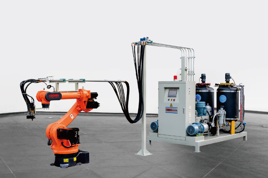
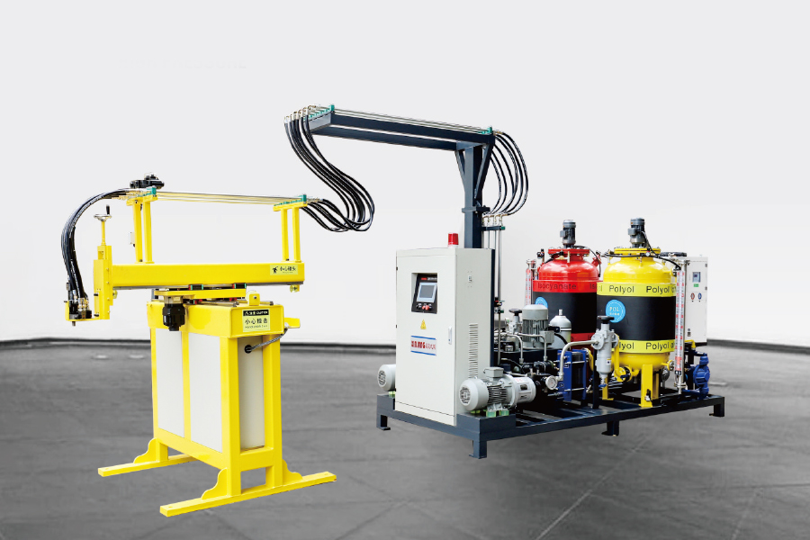
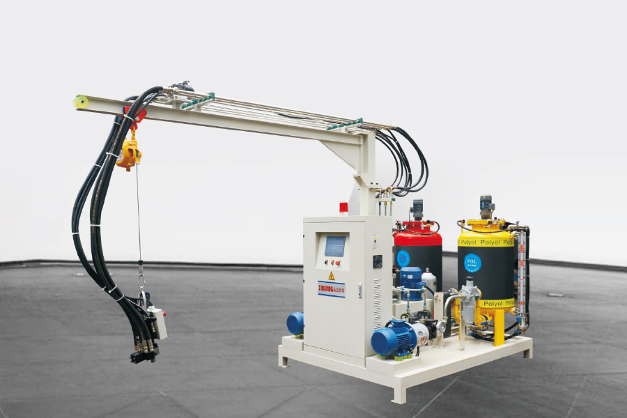
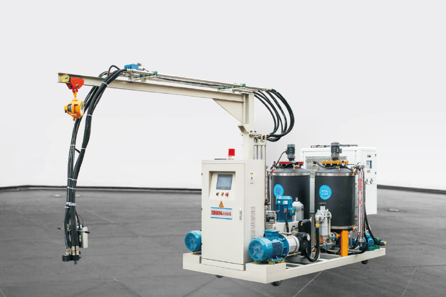
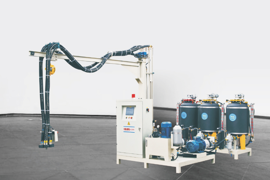
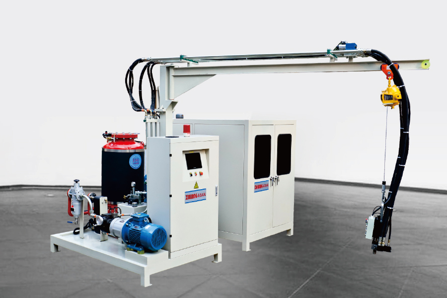
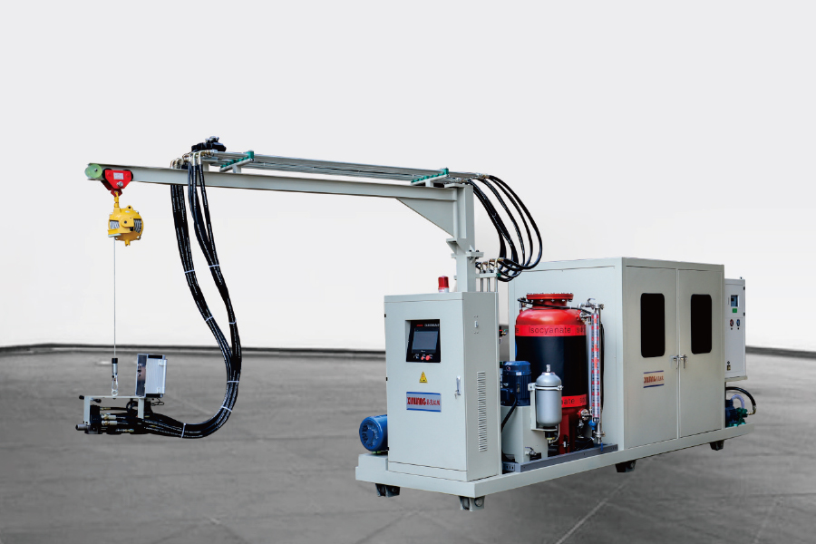
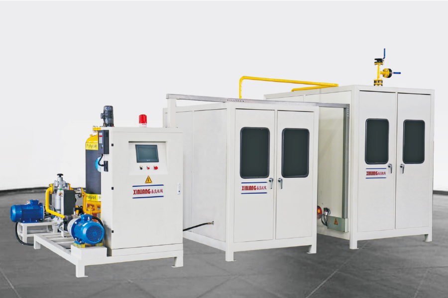
The seven most common PU foam defects are: surface voids and pinholes, collapse or shrinkage, uneven cell structure, delamination, discoloration, dimensional inconsistency, and poor skin formation. Each defect has a specific root cause — and each can be corrected through precise adjustments to raw material ratios, machine parameters, mold temperature, or mixing pressure. This guide covers all seven with actionable fixes drawn from real production environments using Polyurethane High Pressure Foaming Machines and industrial-grade Polyurethane Foam Equipment.
Whether you operate a PU Foam Production Line for automotive interiors, mattresses, insulation panels, or fitness equipment, defect control directly determines yield rates, material efficiency, and customer satisfaction. Understanding what causes each problem — and how equipment settings interact with chemistry — is the foundation of reliable, high-quality foam production in any polyurethane insulation technology application.
Why PU Foam Defects Occur: The Root Cause Framework
Polyurethane foam is produced by reacting isocyanate and polyol components under precisely controlled conditions. The quality of the final foam depends on a chain of interdependent variables: raw material temperature and humidity, mixing pressure and ratio accuracy, mold temperature, pour pattern, and demold timing. A deviation in any single factor can trigger one or more defects — which is why systematic diagnosis is essential before adjusting any parameter.
Industry data from polyurethane foam manufacturing facilities indicates that approximately 68% of all foam defects can be traced to three primary causes: incorrect component ratio (31%), inadequate mixing pressure or temperature (24%), and raw material moisture or contamination (13%). The remaining 32% involve mold-related issues, environmental conditions, and process sequencing errors.
Fig. 1 — Root cause distribution of PU foam defects in industrial production environments. Incorrect component ratio is the single largest contributor, underlining why accurate metering and ratio control in a High Pressure PU Foam Machine is critical. Together, the top two categories account for over half of all defect occurrences, making machine calibration and maintenance the highest-leverage area for quality improvement.
Defect 1: Surface Voids and Pinholes
What It Looks Like and Why It Happens
Surface voids and pinholes appear as small craters or open cells on the foam surface, ranging from barely visible micro-pores to 3–5 mm craters that compromise aesthetic and functional quality. This is one of the most frequently reported defects in PU Insulation Foaming Machine operations and affects applications from decorative strips to automotive headrests.
The primary cause is trapped gas that cannot escape before the foam skin sets. Contributing factors include: excessive mold release agent (creating a barrier that traps air), mold temperature too low (skin forms before gas can migrate to the parting line), raw material moisture content above acceptable limits (>0.05% water in polyol can generate CO₂ bubbles), and inadequate mold venting.
How to Fix It
Raise mold temperature to the recommended range (typically 40–55°C for most flexible foam systems) to slow skin formation and allow gas to escape.
Reduce mold release agent application — use only enough for clean demold, and switch to water-based release agents where possible.
Verify polyol moisture content with a Karl Fischer titration test; moisture above 0.05% requires drying before use.
Check and clear mold vent holes — vents of 0.3–0.5 mm diameter placed at the last-fill point are standard practice.
On the Automatic PU Foaming System, verify that injection pressure is adequate to fill the mold cavity without air entrapment — low pressure extends fill time and increases gas bubble formation.
Defect 2: Foam Collapse and Shrinkage
Identifying Collapse vs. Shrinkage
Collapse occurs immediately after demold — the foam loses height or structure within seconds to minutes because the cell walls are insufficiently cured to support the foam's own weight. Shrinkage is a slower process where the foam dimensions reduce over hours or days as internal gas pressure normalizes. Both are distinct from settage (permanent compression set), though they share some root causes.
Collapse is most commonly caused by premature demold, insufficient catalyst, or incorrect isocyanate index. The isocyanate index (the ratio of actual NCO to theoretical NCO required) for most flexible foam systems should be in the range of 100–115; values below 95 leave too many unreacted polyol chains, producing a weak network that collapses under its own weight. In rigid foam for thermal insulation manufacturing and energy efficient insulation foam applications, an index below 105 is a frequent collapse trigger.
Corrective Measures
Extend cure time before demold — for most flexible foam systems, minimum mold cure time at 45°C is 4–6 minutes; do not demold based on time alone, verify firmness.
Recalibrate component ratio on the High Pressure Foam Mixing Machine; even a 2–3% drift in the A/B ratio can push the isocyanate index outside the acceptable window.
Review catalyst loading — amine catalysts control gel time, tin catalysts control blow time; an imbalance between the two produces weak cell structure prone to collapse.
For shrinkage in rigid foam, check blowing agent concentration; under-nucleated systems produce fewer, larger cells that are more prone to shrinkage as the blowing agent cools.
Defect 3: Uneven Cell Structure
Uneven cell structure — visible as regions of coarse, open cells alongside zones of fine, closed cells within the same foam part — directly affects mechanical properties including tensile strength, elongation, and compressive load deflection. In EV battery insulation foam and lightweight automotive foam applications, cell uniformity is particularly critical because it governs both thermal resistance and vibration damping performance.
The leading cause is inadequate mixing in the mixing head of the PU Foam Injection Equipment. At mixing pressures below 120 bar, turbulent impingement mixing — the mechanism by which high-pressure machines achieve homogeneous blending — becomes insufficient. The result is streaks of poorly blended material with different reactivity and cell structure.
Fig. 2 — Relationship between mixing head pressure and cell uniformity index in high-pressure PU foam production. Below 120 bar, uniformity drops sharply, confirming that adequate impingement pressure is the primary control variable for consistent cell structure. Above 150 bar, further gains are incremental — meaning the 120–160 bar range represents the practical operating window for most Industrial PU Foaming Machine applications. Maintaining this pressure window through regular pump and nozzle inspection is a core preventive maintenance task.
Beyond mixing pressure, material temperature affects viscosity and therefore mixing quality. Polyol components should be maintained at 20–25°C; higher viscosity at lower temperatures requires higher pressure to achieve equivalent mixing intensity. Smart foam production systems incorporating inline temperature monitoring can automatically compensate by adjusting flow rates when material temperature drifts outside the target band.
Defect 4: Delamination Between Foam and Substrate
Delamination — the separation of foam from an insert, skin, or substrate — is a critical failure mode in composite PU parts such as car seats, headrests, and insulation panels. In polyurethane EV applications where foam must maintain consistent adhesion to battery housing materials across wide temperature cycles, delamination is a significant quality and safety concern.
The causes of delamination are generally surface-related: substrate contamination (oils, moisture, dust), insufficient adhesion promoter, incompatible substrate material, or foam system chemistry not matched to the substrate surface energy. Even a fingerprint on an insert surface can reduce adhesion strength by 30–40% in sensitive systems.
Prevention and Correction
Clean all inserts with isopropyl alcohol immediately before placement — do not allow more than 15 minutes between cleaning and foam injection.
Apply appropriate adhesion promoter to low-surface-energy substrates (polyethylene, polypropylene) — corona or flame treatment can also increase surface energy before bonding.
Verify that substrate temperature matches the mold temperature — cold inserts cause local undercure at the interface.
Review foam system compatibility with your substrate — some polyurethane systems require specific surfactant packages to achieve adequate wetting of the substrate surface.
Defect 5: Discoloration and Yellowing
Discoloration in PU foam takes two primary forms: yellowing of light-colored or white foam shortly after production, and localized dark or brown streaks within the foam mass. Both have distinct causes and require different corrective approaches.
Yellowing is primarily caused by UV exposure, thermal oxidation, or the use of aromatic isocyanates in applications where color stability is required. Aromatic MDI and TDI are known to yellow rapidly on UV exposure — for visible parts requiring long-term color stability, aliphatic isocyanates (HDI, IPDI) must be used. Dark streaks within the foam body typically indicate localized overheating from an excessively reactive catalyst system or insufficient heat distribution during the reaction.
For exterior or light-exposed applications, reformulate with aliphatic isocyanate or add UV stabilizers and hindered amine light stabilizers (HALS) to the polyol blend.
Dark streak defects: reduce catalyst loading by 0.1–0.2 php (parts per hundred polyol) and verify that the mixing head temperature is not causing premature reaction initiation at the nozzle.
Ensure raw material storage areas are dark and temperature-controlled — polyol and isocyanate components exposed to light or heat above 30°C before use may show accelerated discoloration in the final product.
Defect 6: Dimensional Inconsistency Across Production Runs
Dimensional inconsistency — where foam parts from the same mold vary in height, width, or density between shots — is a production efficiency and quality problem that becomes increasingly costly at scale. A 5% variation in foam density across a batch translates directly to wasted raw material and inconsistent product performance. For automatic foaming machine operations producing hundreds of parts per shift, even small inconsistencies accumulate into significant scrap rates.
Fig. 3 — Average foam density variation attributed to six process factors in industrial PU foam production. Component ratio drift produces the highest variation at 7.2%, reinforcing that precise metering is the most critical control point in any PU Foaming Injection Machine. Material and mold temperature are the second and third most significant contributors — both highly manageable with modern automatic foaming machine controls that incorporate closed-loop temperature regulation and continuous ratio verification.
Correcting dimensional inconsistency requires a systematic approach. Start by logging density measurements shot-by-shot over a 50-part run to identify whether the variation is random (suggesting a random process variable like temperature fluctuation) or systematic (drifting in one direction, suggesting pump wear or calibration drift). Industry 4.0 polyurethane systems with real-time process data logging make this analysis straightforward and dramatically reduce the time to root cause.
Defect 7: Poor Skin Formation and Surface Roughness
The foam skin — the dense outer layer that forms against the mold surface — determines the part's appearance, tactile quality, and abrasion resistance. Poor skin manifests as roughness, thin or absent skin zones, or a chalky, powdery surface texture. For automotive interiors, mattress covers, and fitness equipment components, skin quality is as important as the bulk foam properties.
Skin quality is primarily controlled by mold surface temperature and the foam system's surfactant package. Mold temperatures below 35°C cause the skin to form too quickly and densely before the foam has fully filled the mold, resulting in cold spots and rough texture. Mold temperatures above 60°C for most flexible systems allow the skin to remain fluid too long, thinning the skin and potentially causing surface porosity.
Target mold surface temperature of 42–52°C for most flexible integral-skin applications; use precision mold temperature controllers rather than relying on ambient heating.
Verify that the mold surface finish is consistent — scratches, pitting, or residue buildup from inadequate mold maintenance will transfer directly to the skin surface texture.
Review silicone surfactant loading — insufficient surfactant produces coarser surface cells; excessive surfactant can cause skin collapse or tackiness.
For integral-skin formulations, ensure that the physical blowing agent (cyclopentane or HFC) concentration is optimized — too little blowing agent yields a thick, heavy skin; too much produces a foamy skin with visible cell windows.
Defect Frequency and Impact: A Comparative Overview
Understanding which defects are most common and which have the greatest impact on production efficiency and product quality helps teams prioritize their quality control efforts. The table and radar chart below summarize the seven defects covered in this guide across three critical dimensions.
Summary of seven PU foam defects: frequency, impact severity, and primary control variable
Defect
Occurrence Frequency
Impact on Quality
Primary Control Variable
Correction Difficulty
Surface Voids / Pinholes
Very High
Medium
Mold temperature & venting
Low
Collapse / Shrinkage
High
High
Isocyanate index & catalyst
Medium
Uneven Cell Structure
High
High
Mixing pressure
Low–Medium
Delamination
Medium
Very High
Surface preparation & chemistry
Medium
Discoloration
Medium
Medium
Isocyanate type & UV exposure
Low
Dimensional Inconsistency
High
High
Component ratio & temperature
Medium–High
Poor Skin Formation
Medium
Medium–High
Mold temp & surfactant
Low–Medium
Fig. 4 — Radar chart scoring seven PU foam defects by their combined impact on product quality and production efficiency (scale: 1–10). Delamination scores highest at 10 because it typically causes complete part rejection with no rework option. Collapse and dimensional inconsistency follow at 9 and 8 respectively. The radar shape illustrates that no single defect dominates all dimensions — a comprehensive quality program must address all seven to achieve consistent production yields on a Polyurethane Foam Production Line.
How the Right PU Foaming Equipment Prevents Defects at the Source
Many of the defects described above are preventable through equipment design rather than process adjustment. A well-specified Polyurethane High Pressure Foaming Machine or Automatic PU Foaming System incorporates features that address the root causes of each defect category proactively.
Closed-loop ratio control: Continuous flow measurement on both A and B streams with automatic correction maintains component ratio within ±0.5% — directly reducing the largest single source of density variation and collapse risk.
High-pressure impingement mixing: Operating at 120–200 bar ensures thorough mixing in milliseconds without mechanical mixing heads that require maintenance and cleaning — the basis for uniform cell structure in every shot.
Temperature-controlled material circuits: Precision heating and insulation on raw material supply lines and tanks maintains polyol and isocyanate at target temperature regardless of ambient conditions — essential for consistent reactivity in multi-shift production.
Programmable shot profiles: Variable injection rate and pressure profiles — available on advanced PU Foam Injection Equipment — allow operators to optimize fill patterns for complex mold geometries, reducing void and delamination risk.
Process data logging: Real-time recording of pressure, temperature, flow rate, and shot weight for every cycle enables statistical process control (SPC) and rapid root cause analysis when defects occur.
Ningbo Xinliang Machinery Co., Ltd. designs and manufactures Polyurethane High Pressure Foaming Injection Machines and complete Polyurethane Foam Production Lines that incorporate all of these features. With over ten years of continuous R&D refinement and production experience, Xinliang's systems are compatible with 141B, F11, water foaming, and cyclopentane foaming methods, covering applications from automotive interiors and car seats to mattresses, fitness equipment, and EV battery insulation foam. As a professional custom manufacturer and OEM supplier, Xinliang provides comprehensive technical support from consultation through commissioning and after-sales service.
Frequently Asked Questions
Q1. What causes pinholes on the surface of PU foam parts?
Pinholes are caused by small gas bubbles trapped near the mold surface before the skin sets. The most common causes are excessive mold release agent creating a barrier layer, mold temperature too low (causing rapid skin formation before gas escapes), and polyol moisture content above 0.05%. Corrective steps include raising mold temperature to 42–52°C, reducing release agent volume, clearing vent holes, and testing raw material moisture. In most cases, pinholes can be eliminated within a few trial shots once the mold temperature is properly set.
Q2. Why does my PU foam collapse after demolding?
Collapse after demold usually indicates that the foam network is insufficiently cured to support its own structure at the point of demold. The three most common causes are: premature demold before adequate gel time has been reached, incorrect isocyanate index (typically below 100 for flexible foam), and catalyst imbalance where blow catalyst exceeds gel catalyst loading. Begin by extending cure time by 30–60 seconds per trial; if collapse persists, verify the A/B ratio on your foaming machine with a catch-weight test and compare against the system formulation specification.
Q3. What mixing pressure should a high pressure PU foam machine operate at?
For most flexible and rigid polyurethane foam systems, the recommended operating pressure range for impingement mixing is 120–200 bar. Below 120 bar, turbulent mixing becomes insufficient and streaky, uneven cell structure results. Above 200 bar, the benefits diminish and wear on nozzle components increases. Most production processes operate in the 140–170 bar range as a practical optimum. For systems with high-viscosity polyol components (above 3,000 mPas at 25°C), the upper end of this range or material preheating to reduce viscosity is recommended.
Q4. How do I prevent PU foam from yellowing?
Yellowing in PU foam is most commonly caused by UV exposure oxidizing the aromatic isocyanate-derived segments of the polymer. For applications where color stability is required — particularly white, cream, or light-colored parts exposed to light — reformulate using aliphatic isocyanates (HDI or IPDI) or add UV stabilizers and HALS additives to the polyol blend. For interior parts not exposed to UV, ensure that raw materials are stored below 25°C away from light sources, as pre-exposure can cause latent yellowing in the final part even without UV exposure during use.
Q5. What is the difference between a high pressure and low pressure PU foaming machine?
High pressure foaming machines mix components by impingement — two high-velocity streams collide and mix in a small mixing chamber without a mechanical mixing element. This produces excellent mixing quality, is self-cleaning, and handles a wide range of reactivity systems. Low pressure machines use mechanical agitators to mix lower-pressure streams and are better suited for slow-reacting, high-filler, or very high-viscosity systems. For most flexible foam, rigid foam, and integral-skin applications, high pressure machines offer superior mix quality, lower maintenance, and better repeatability — which is why the High Pressure PU Foam Machine is the industry standard for quality-critical production.
Q6. How often should PU foaming machine nozzles and mixing heads be inspected?
Nozzle and mixing head components should be visually inspected at the start of every shift for wear, blockage, or chemical buildup. Dimensional inspection and replacement of wear parts (orifice nozzles, control rods, seals) should be performed according to the machine manufacturer's schedule — typically every 500,000 to 1,000,000 shots for high-quality components, or earlier if pressure drop across the mixing head changes by more than 5% from baseline. Worn nozzles are a leading cause of mixing quality degradation and are the first component to check when cell structure defects appear suddenly in an otherwise stable production process.


 English
 русский
 عربى
عربى